Glass polishing: Eliminating the development of grooves during polishing
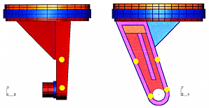
Because grooves occurred during the polishing process of eye glasses, the operating vibration behavior on a glass polishing machine was investigated. The top figure shows the plate, which supports the motor. The tool shaft (bottom) is driven by a toothed belt, operating within the swivel arm. The yellow points mark the measuring points.
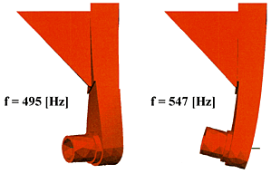
The unbalance of the motor, the flapping of the belt and the tool gearing lead to resonance related excitation of the swivel arm. The center figure (FEA results) illustrates the torsion at 495 [Hz] and the bending of the swivel arm at 547 [Hz]. These vibration mode shapes are substantially responsible for the development of grooves.
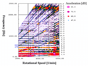
The bottom figure shows the operating vibration during the polishing process in Campbell representation. The rings running parallel to the speed axis mark the natural frequencies of the polishing machine. The beams running up diagonally reflect the orders of excitation.
The natural frequencies of the torsion and the bending of the swivel arm move together during the polishing process under certain operating conditions. In some cases this can lead to such high vibration magnitudes that the limit for the dynamic stability during tool/glass contact is exceeded, causing grooves in the glass.
The following measures could reliably eliminate the development of grooves during the polishing process: a die cast profile with reinforcements on both sides to stiffen the torsion of the arm, a better guide of the toothed belt and minimizing the unbalance of the motor. The optimized guide of the toothed belt could also minimize the effect of the electromagnetic motor power of the order of excitation EO=8 on the tool. Finally, all polishing machines were subject to these changes.
Our specialists are always at your disposal to flexibly respond to your respective requirements and wishes.
Dr. Michael Elbs, Managing Director


Measuring points on the swivel arm

2nd and 3rd mode shape of the swivel arm

Campbell-diagram: run-up of an unbalanced motor

