Speed controler of a mobile crane
During the layout of control systems for mechanic drives, the detailed dynamic behavior of the controlled system should be considered. This applies in particular if several motors are controlled in master-slave-configuration. In this mode, the speed of one single motor represents the control variable, while all three motors are final control elements.
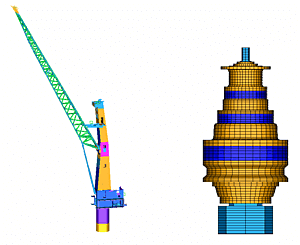
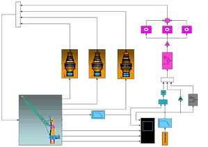
The investigated example is a speed controller for the slewing gear of a mobile harbor crane. As a first step an FEA model of the crane was created. This model includes the complete support structure and in particular the dynamic properties of the three slewing gear drives. This detailed dynamic model of the controlled system was transferred to MATLAB/Simulink as a modal reduced system. Inside MATLAB/Simulink, the feedback control system, a PID controller with feed forward, was implemented (mid figure).
With this detailed model of the feedback control system optimum control parameters were determined. On the one hand, the control stiffness should be maximized for an optimum operability. On the other hand, a sufficient safety margin is required against any control instability.
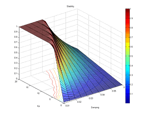
The mechanical damping and the proportional amplification near the torsional frequencies of the slewing gear drives are the main parameters determining the stability of the controller. If the proportional amplification is too high, the out-of-phase torsional modes of the slewing gear drives become unstable. The bottom figure shows the derived stability map of the feedback control system. Tests confirmed the predicted behavior.
Our specialists are always at your disposal to flexibly respond to your respective requirements and wishes.
Dr. Michael Elbs, Managing Director


FEA model of the mobile crane (left) and of a single slewing gear drive (right)

MATLAB/SIMULINK model of the speed controler

Stability map of the feedback control system

