Thermal layout of a temperature controller
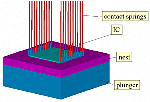
During the operating test of ICs, their temperature should be controlled within 0.5 [K]. It should be investigated, if and with what requirements such a controller unit can be designed. The principle mechanical setup includes the plunger which can be heated or cooled, the movable nest with the IC and contact springs for contacting the IC to the electronic test equipment.
The plunger and the nest can be designed with several materials and dimension according to the thermal requirements. The length of the contact springs differs according to the test application. The ends of the contact springs opposed to the IC are nearly at ambient temperature.
First pre-studies showed that the thermal behavior of the controller unit strongly depends on the thermal contact resistances between plunger and nest as well as between nest and IC and on the length of the contact springs. Special coatings of the nest and plunger and blowing the contact springs with tempered air significantly improves the performance of the controller unit.
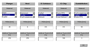
For a coarse layout of the controller unit by the designer, a simulation program based on MATLAB was developed. The user enters dimensions, material properties, contact data and thermal boundary conditions like heat loads, temperatures and flow conditions for the contact springs. As an example, the center figure shows the input form for the dimensions and the material mapping.
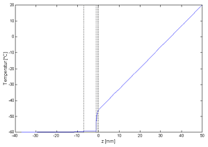
The program automatically builds up a Finite Difference (FDA) model of the controller unit. As results, the user obtains the thermal resistances and the temperature distribution as shown in the bottom figure.
Our specialists are always at your disposal to flexibly respond to your respective requirements and wishes.
Dr. Michael Elbs, Managing Director


Principle mechanical setup of the temperature controller

Input form for dimensions and material mapping

Output window: Temperature distribution along height

