Compressor
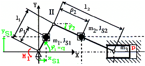
The rigid body system, as shown in the top figure is used to simulate vibrations of a compression stage. The elastic properties of the drive, however, are not taken into consideration. Due to the kinematical relations between crank (1), piston rod (2) and piston (3), the system can be reduced to a single degree of freedom q, which describes the revolution of the crankshaft.
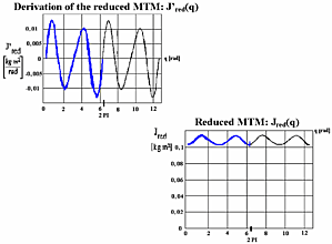
All mass parameters can be reduced to an inertia moment Jred(q) depending on the angle of rotation. The center figure shows for example the course of Jred(q) for two revolutions of the crankshaft. The variable moment of inertia enters into the reduced dynamical equation with the first derivation J’red(q) and the rotation speed squared. This causes the development of rotational harmonics.
The propulsion of the compression stage is represented via a constant torque of the crankshaft M1. In addition, the compression and depression of the compression volume is taken into account, whereas the gas intake and discharge is not.
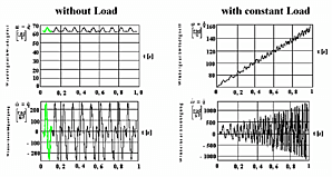
The nonlinear dynamical equation can be solved under these assumptions. In a load-free situation, the angular velocity varies, as shown in the bottom figure. Rotational oscillations superimpose the constant revolution. The resulting angular accelerations are strongly characterized by the first and second order of excitation. Compared to the first order of excitation, the second delivers much smaller magnitudes in the lower speed range.
In the case of a constant outer torque M1, the compressor will be accelerated. The vibration magnitude of the second order of excitation rises with an increasing rotational speed as opposed to the first order of excitation. This is due to the quadratic term in the dynamical equation.
Our specialists are always at your disposal to flexibly respond to your respective requirements and wishes.
Dr. Michael Elbs, Managing Director


Diagrammatic sketch and coordinate definitions

Varying moment of inertia


Angular velocity and angular acceleration

