Automobile component: engine mount
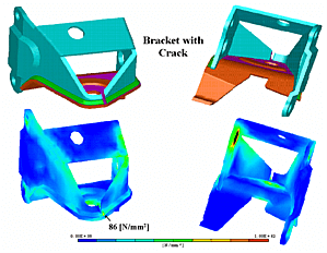
On the test stand, vibration caused cracks occurred on the engine mount of the VR6. Therefore, the welded design, a shoe-shaped bent plate as the upper half (cyan) welded (green) to the bent back bottom part (orange) was investigated.
Starting situation:
The engine mount was tested for operational stability on a test stand. The suspension bracket was held on four reference points at the upper shoe half (cyan). In order to apply forces, a piston was screwed onto the bottom half. Via the piston, the structure was driven by dynamic load.
Cracks at the front shoe area, starting at the gap, were often observed during the test.
Theoretical Investigation:
FEA simulations showed alternating stress magnitudes of 86 [N/mm2] at the peak of the gap. This would be too high for the engine mount under continuous load. Therefore, it was investigated, if closing the gap leads to a reduction of the dynamic stress magnitudes.
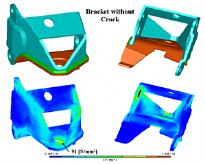
The results of this design variant are shown in the bottom figure. It shows that after welding the gap, the maximal dynamic stress lies even higher (91 [N/mm2]) than for the original variant.
Improvement:
On closer examination of the test stand, it turned out that the cracks formed during the operational stability tests were induced by the test stand. It was determined that the installation of the engine mount to the test stand and the type of force application was too rigid compared to the actual assembly situation in the car.
As a result of the investigations, the test stand was modified to better meet the assembling conditions in the car.
Our specialists are always at your disposal to flexibly respond to your respective requirements and wishes.
Dr. Michael Elbs, Managing Director


Engine mount VR6

Engine mount VR6 (modified)

