Thermal behavior of an electric motor
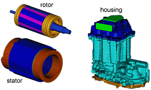
In order to gain detailed insight into the thermal behavior of the drive motor of an electric car, a thermal FEA model of this motor was created. The FEA models of the motor’s components are shown in the top figure.
Transient temperature data obtained from measurements on the subsystems rotor and stator with housing were compared with equivalent simulation results in order to determine the relevant thermal coupling parameters in detail. Besides the coupling between the windings and the lamination stacks, the pressure fit between stator stack and housing was found to be of importance.
CFD simulations at various rotation speeds were performed in order to determine the thermal coupling between rotor and stator. As shown in the mid figure, vortices already occur at moderate speed. At maximum speed, these vortices improve the thermal coupling between rotor stator compared to the pure shear flow conditions by a factor of 5. These flow instabilities are called Taylor vortices in the literature.
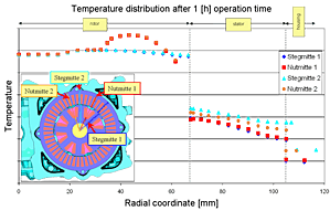
The bottom figure shows the spatial temperature profile after 1 hour of operation along the radial coordinate of the motor. Despite the improvements due to the Taylor vortices, the coupling between the rotor and stator represents the highest thermal resistance. This results in a large temperature difference between rotor and stator of approximately 50 [K]. Additionally, the coupling between rotor stack and rotor winding as well as the radial conductance through the stator stack and the shrinkage coupling between stator and housing contribute significantly to the maximum temperature at the rotor winding.
Our specialists are always at your disposal to flexibly respond to your respective requirements and wishes.
Dr. Michael Elbs, Managing Director


Thermal models of rotor, stator and housing

Fluid flow within the air gap between rotor and stator (rotating frame of reference)

Temperature profile across rotor and stator after 1 hour of operation

